[Home] [Digital Signal Processing route] [Published Articles]
[Local QRM/noise reduction] [Very small vertical magnetic loop]
[Medium size vertical magnetic loop] [Vertical magnetic Alford loop]
[Vertical magnetic loops in real life] [Circular polarization]
[Broadband amplification] [Broadband amplifier] [Single chip amplifier]
[Dual loop antenna system] [Hints]
[Phaser 80 – 10 meters] [Balancing and closed loop antennas]
The (mini) whip in EZNEC Pro2+
EZNEC Pro2+ v7.0 is free available since January 2022. The Pro version has a “plane wave source” that generates an electrical field at infinite distance.
The field strength E, polarization, elevation and azimuth direction can be set. With this source EZNEC is much better equipped to do calculations on receiving antennas like active loops and vertical monopole antennas like (mini) whip antennas.
Antenna A on page http://www.pa0sim.nl/Local%20QRM%20reduction.htm is an example of a whip antenna.
EZNEC Pro2+ v7.0 is now used to further zoom in on the behavior of the (mini) whip.
The EZNEC files are available in EZNEC_files_PA0SIM.zip
Effective height heff of a whip antenna.
Effective height or effective length [1, 2] is a well-known measure of response of antennas.
We start examining the next three whip antennas:
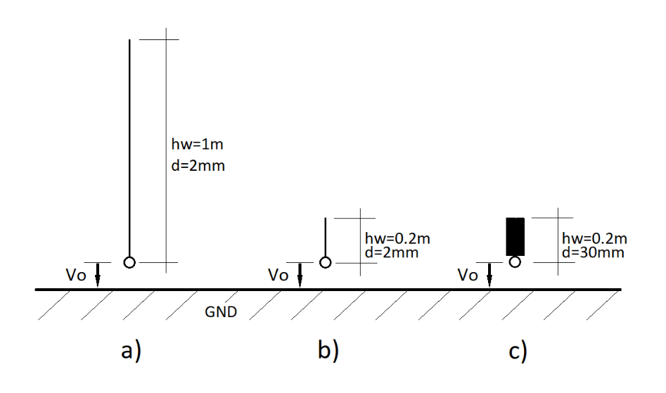
Fig.1. a) whip d=2mm hw=1m b) mini whip d=2mm hw=0.2m en c) mini whip d=30mm hw=0.2m
All three antennas are vertical monopole antennas. The actual height is hw and the diameter is d. Mounted at ground level (GND) the effective height heff can be calculated by:
heff = Vo / E
Vo is the open-circuit voltage (V) and E the electrical field strength (V/m) of a vertical polarized field.
As long as the actual height is small compared to the wavelength, the effective height heff of a short monopole antenna equals half the actual height hw:
heff = 0.5 × hw
So the expected effective heights for the three whip antennas are:
heff = 0.5m, 0.1m and 0.1m
Measurement setup in EZNEC at 7MHz
In order not to make it too complex, we use ideal ground. The antennas have to stay small compared to the wavelength, so the frequency should not be too high. But the frequency should not be too low also, because of limitations in the calculating engine in EZNEC. A measurement frequency of 7MHz is used.
Generating a vertical polarized electrical E field.
EZNEC Pro2+ v7.0 has a plane wave source that generates an electrical field at infinite distance.
The field strength E, polarization, elevation and azimuth direction can be set.
When using ideal ground, for a 1V/m field strength of a vertically polarized field at the receiving antenna, we need to set a 0.5V/m field strength for the plane wave source (see EZNEC manual [3]).
For a field strength of 1V/m the open-circuit voltage equals the effective height heff.
Measuring the open-circuit voltage Vo
For now we assume the amplifier behaves like an ideal voltage follower with gain=1 and an infinite input impedance (no capacitance). We can then use a large 1MOhm resistor RL instead of the amplifier. The open-circuit voltage Vo is the voltage across this resistor RL. “Load Data” gives this voltage.
Measuring field strength as a function of height.
The “Near Field” tab calculates the field strength including all polarization information.
The plane wave source however cannot be used. You have to generate a vertically polarized field yourself by using for instance a vertical dipole at a distance of 400m. A 10m long vertical dipole at 400m distance actuated by a 8.56A current source generates a 1V/m electrical field over ideal GND. EZNEC shows that the field strength of a vertically polarized field is practically independent of height.
Verification of effective height of the (mini) whip antennas.
The by EZNEC measured open-circuit voltages Vo across RL for the three whip antennas in fig.1. are:
Vo = 0.5059, 0.1165 and 0.1168 Volt
Because the electrical field strength is 1V/m, this equals the effective height heff. These values match the calculated values for heff well for all three (mini) whip antennas. Because the very short mini whip antennas have only a few segments, the results are less accurate, but still usable.
As the field strength is equal at different heights, the lower voltages measured by the very short mini whip antennas are not a result of a lower field strength but of the lower effective height.
Note: the open-circuit voltage practically doesn’t increase when increasing the diameter and capacitance of the mini whip.
Effective height of the (mini) whips antennas at mast height hm.
The same three antennas, but now on a grounded 2m high mast. Depending on construction, the coaxial cable outer conductor constitutes the mast or in combination with the electrical conducting mast. RL represents the amplifier.
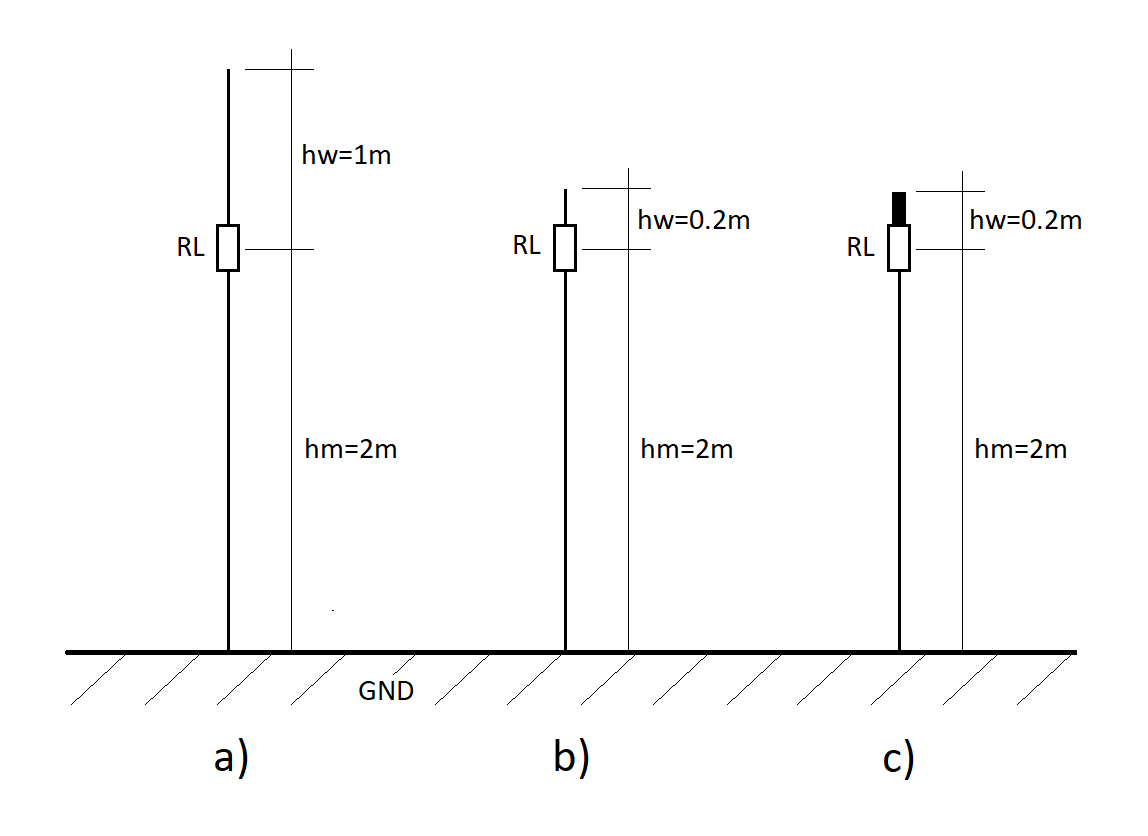
Fig.2. Mast height 2m with a) whip d=2mm hw=1m b) mini whip d=2mm hw=0.2m en c) mini whip d=30mm hw=0.2m
The effective height with mast [4, 5, 6, 7] now is:
heff = 1×hm + 0.5×hw
The coaxial outer conductor mast behaves also like a whip antenna (vertical monopole).
However the contribution of the mast hm accounts for “1”, because it is grounded and held electrically at 0 Volt ground potential. If we could disconnect the mast from ground, this multiplier would be also “0.5”.
The measured voltages across RL are now:
Vo = 2.51, 1.99 and 2.02 Volt
The open-circuit voltage Vo equals again the effective height heff.
The contribution of the mini whip antennas is much lower than of the coaxial outer conductor mast.
Thus the lower accuracy of the very short mini whip contribution becomes less relevant.
The height of the mast dominates the received open-circuit voltage and the effective height heff.
The (mini) whip antenna at higher frequencies
The sweep function of EZNEC is used to measure the response on higher frequency bands.
A sweep is made from 3MHz up to 100MHz in 0.5MHz steps. On each frequency the open-circuit voltage Vo is measured at a 1V/m field strength of a vertically polarized field. Vo equals the effective height heff.
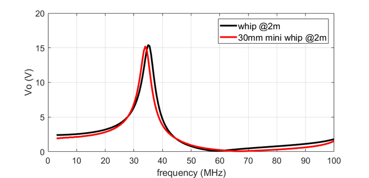
Fig.3. Heff between 3MHz-100MHz of the whip and the 30mm mini whip on a 2m mast.
The frequency of the peak is mainly set by the height of the mast. The received voltage Vo increases considerably and can overload the amplifier.
Note also both minimums around 60MHz!
Impact of the input capacitance of the amplifier
Up until now we have assumed the amplifier has a zero input capacitance Campl and an infinite input resistance RL. The input capacitance Campl constitutes a voltage divider with the capacitance Cant of the (mini) whip and mast combination. As a result the voltage at the input of the amplifier (Vin) is reduced and the relative noise contribution of the amplifier increases (Fig 4).
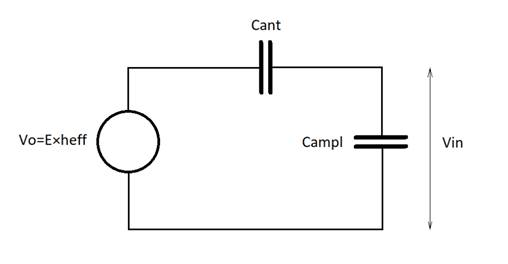
Fig.4. Voltage divider whip capacitance Cant and amplifier input capacitance Campl.
Often the total input capacitance Campl (including all parasitic capacitances) is not accurately known or well controlled. This results in a not well known and controlled contribution to the effective height and so to the relative noise contribution of the amplifier. However the input capacitance doesn’t change the behavior of a (mini) whip.
The capacitance of the whip directly above ground can be measured by replacing the RL by a source. The “Source Data” includes the impedance of the whip. The capacitance of the 0.2m long 30mm mini whip is about 5pF. The effective capacitance of the whip on a mast however is about half!
The contribution of this input capacitance can be measured in EZNEC by adding a capacitor in parallel to the resistor RL. In fig.5 the effective height heff is plotted for a 30mm mini whip with and without a small 2pF capacitance for a frequency sweep between 3MHz and 100MHz.
The input capacitance not only reduces the effective height and the voltage, but also the frequency of the resonance peak.
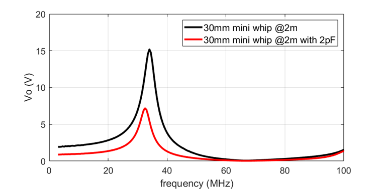
Fig.5. Heff between 3-100MHz of the 30mm mini whip with and without 2pF on a 2m mast.
Location of the amplifier
If we set the amplifier to a lower height, keeping the same total height, the effective height will decrease. With the amplifier at the bottom of the mast the effective height equals half the actual height of the mast including whip height. The contribution of the input capacitance is the lowest at the bottom of the mast. Depending on the input capacitance, the best location of the amplifier for best SNR, is not at the top of the mast [4, 5].
Impact diameter of the mast and (mini) whip
Diameter of both the mast and the (mini) whip in combination affect the effective height. Sensitivity to it can be examined in EZNEC very well. May be not that accurate, but good enough.
Disadvantage of the sensitivity is that it affects the predictability of the effective height and so the relative contribution of the amplifier noise.
Polarization
Vertical monopole antennas receive the vertical polarization component of signals.
An active whip antenna is mounted close to the ground compared to the wavelength. The field strength of a horizontal polarized component depends on height and is minimal at ground level. It is possible to receive also horizontally polarized signals by sloping the mast, but only with reduced signal strength.
Using a trans-impedance amplifier
Instead of a voltage follower a trans-impedance amplifier can be used also [8]. The short-circuit current is measured instead of the open-circuit voltage. A capacitor is used in the feedback setting the gain and heff.
The total height of the mast and whip now set the (lower) frequency of the peak in fig.3.
Conclusions
With some care it is possible to simulate and verify the behavior of the mini whip in EZNEC with useful results. But it is on the edge with the NEC-2D calculating engine. Precondition is knowledge about the behavior of the mini whip as a vertical monopole.
The (mini) whip is a vertically polarized omnidirectional receiving antenna. The mini whip is nothing more than a very short vertical monopole.
When mounted on a mast, the (mini) whip antenna is not the only antenna.
The coaxial outer conductor and mast are the dominating part and are, in fact, the main antenna!
The mini whip contribution to the signal strength is practically negligible.
The mini whip can therefore be regarded as a capacitive top loading, necessary to measure the voltage with the amplifier.
A few short horizontal radials, instead of the mini whip, can be used also.
Depending on the noise contribution of the amplifier, a mast with a certain height is needed.
The mast gives rise to possible overloading of the amplifier by signals at the resonance peak in the effective height heff.
When mounted on a building, the resonances of the building will affect the signal levels too. The building also behaves like a large vertical monopole antenna.
The mast and coaxial outer conductor have to be grounded well to have predictable signal levels and to minimize receiving local noise arriving via the coaxial outer conductor.
References:
[1] https://en.wikipedia.org/wiki/Aperture_(antenna)#Effective_length
[2] “Antennen” Band 1, 1977, Edmund Stirner, pg 146 and 200
[3] Manual EZNEC: https://www.eznec.com/ez70manual.html
[4] H.Lindenmeier “Die Transistorierte Empfangsantenne mit kapazitiv hochohmigen Verstärker als optimale Lösung für den Empfang niedriger Frequenzen”, Nachrichtentechn. blz. 29 Heft 1. 1976
[5] H.Lindenmeier, AGARD Lecture series No.131 1983 chapter 5-1: https://apps.dtic.mil/sti/pdfs/ADA135087.pdf#page=66
https://www.leobaumann.de/Theorie_aktiver_Antennen.pdf
The Handbook of Antenna Design Volume 2, pg. 639, ISBN 0-906048-87-7
[8] E.H.Northolt, “Breedbandige actieve antennes voor 5kHz tot 30MHz”, pg. 65-77, Elektronica 1981 nr. 7.
Further reading:
https://www.dl4zao.de/_downloads/Monopol_und_Dipol_Aktivantennen_SWT2018.pdf
https://analog-electronics.tudelft.nl/downloads/NordholtActiveAntenna.pdf
https://owenduffy.net/antenna/PA0RDT-MiniWhip/
[up]
Last update: December 31, 2022
© PA0SIM