[Home] [Digital Signal Processing route] [Published Articles]
[Local QRM/noise reduction] [Very small vertical magnetic loop]
[Medium size vertical magnetic loop] [Vertical magnetic Alford loop]
[Vertical magnetic loops in real life] [Circular polarization]
[Broadband amplification] [Broadband amplifier] [Single chip amplifier]
[Dual loop antenna system] [Hints]
[Phaser 80 – 10 meters] [Balancing and closed loop antennas]
A Two-Transistor Phaser for 80 – 10 meters (update March 2019 of 2006 design)
After using the MFJ-1025 Noise Canceling box for a few years, I noticed that I really did not use it in the array application. Mainly because it is not well-equipped for the job. It is difficult or impossible to find the right settings for the phase difference and gain ratio.
On this page I present a more useful Phaser or Noise Canceller.
Phaser is a better name for it when using it in an array application.
Desirable Phaser specifications
phase control
· must cover the full 360°
· linear scale for maximum phase control spreading **
· knowledge of the actual phase setting
· logical scale for application in an array (linear from -90° via 0° to +90°)
· reproducible and stable control
gain control
· implemented as a balance (ratio) control
· accurate by using a gain control spreading **
dynamic range
· good large signal behavior
· negligible noise contribution
broadband
· phase and gain both frequency independent
(gain and phase control must be also independent)
cost
· easy to build and no expensive components
** phase and gain control spreading is essential for obtaining deep nulls. Just like bandspreading is for accurate frequency control.
Phasing network
The MFJ-1025, but also the ANC4, uses a well known phasing network to control the phase from one of the antennas. The phase shift is controlled by a variable resistor.
The next schematic shows the circuit used in the MFJ-1025 and the ANC4.
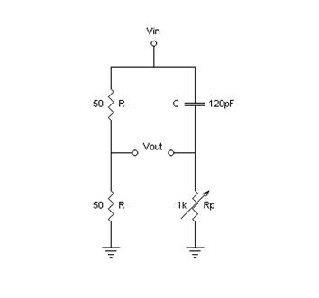
The next graph shows the phase shift at 10MHz as a function of the variable resistor Rp.

The main problems of this circuit are clear. It is not possible to cover the full 180° and the control of the phase shift is very non-linear with the variable resistor. And at other frequencies this non linear behavior is different, so it is not practical to calibrate the scale.
Linear phase shift
It is possible to get an almost perfect linear phase shift when using this circuit for both antenna signals. How: by controlling the phase shift of both antenna signals in the opposite direction at the same time with one single knob.
The next schematic shows the basic new transformed circuit using a differential capacitor (Ca and Cb) for tuning the phase shift. A variable capacitor makes a much better control than a variable resistor (contact wear out).
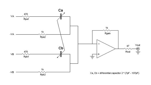
The next graph shows the phase difference at 10MHz as a function of the differential capacitance (Ca or Cb) setting.
At 10MHz and below it is very linear. At higher frequencies, up to 28MHz, it becomes some what less linear. The full 180° is easy feasible!
The next graph shows the phase shift over frequency for 11 capacitor values (7pF, 17pF, …., 107pF).
A Two-Transistor Phaser for 80 – 10 mtr (update March 2019 of 2006 design)
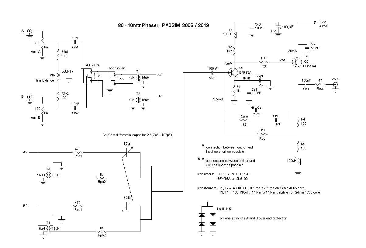
Update: removed Rpa3, Rpa4, Rpb3, Rpb4, Cpa1, Cpa2, Cpb1, Cpb2 which were in parallel with Rpa1, Rpa2, Rpb1 and Rpb2.
The amplitude of antennas signals A and B are first set by Pa and Pb and then the exact ratio is set by the fine balance control Pfb. If using the broadband antenna amplifier no overload protection is necessary. Switch S1 exchange the antennas A and B. Switch S2 inverts one of the antenna signals and makes the other 180° possible. Relays can be used instead of switches.
Notes:
-- The differential capacitor can also be constructed using two normal tuning capacitors. The controlling knob must be isolated (some distance) from the capacitors.
-- A differential capacitor with e.g. a lower value can also be used, but the Rpa1, Rpa2, Rpb1 and Rpb2 resistors have to be scaled. A 5pF-70pF differential capacitor (1.5×smaller) needs 1.5× larger resistors. The output voltage levels will decrease accordingly.
-- Other decent low noise 50 Ohm amplifiers with about 20-30dB gain will also do the job. For the transformers other appropriate cores can be used also, the inductances are very not critical.
-- The functionality can be tested by applying a small signal to the A or B input. The phase at the output should vary over at least 90 degrees on all bands over the full capacitance range of Ca/Cb. By connecting the signal to both inputs A and B (using the same coaxial cable length) the cancelling of the signal should occur at about 180 degrees (Ca=Cb).
Two pictures of the Phaser/Noise Canceller prototype:
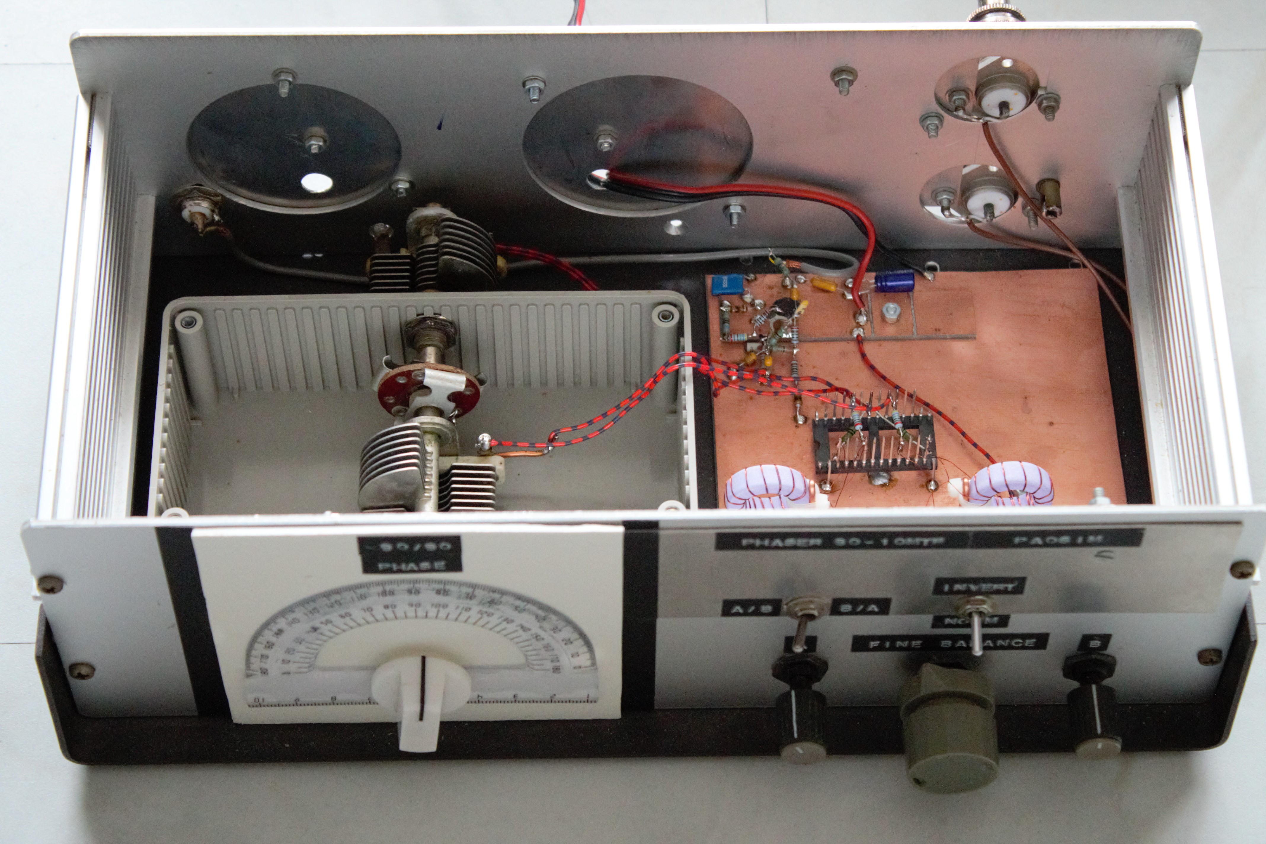
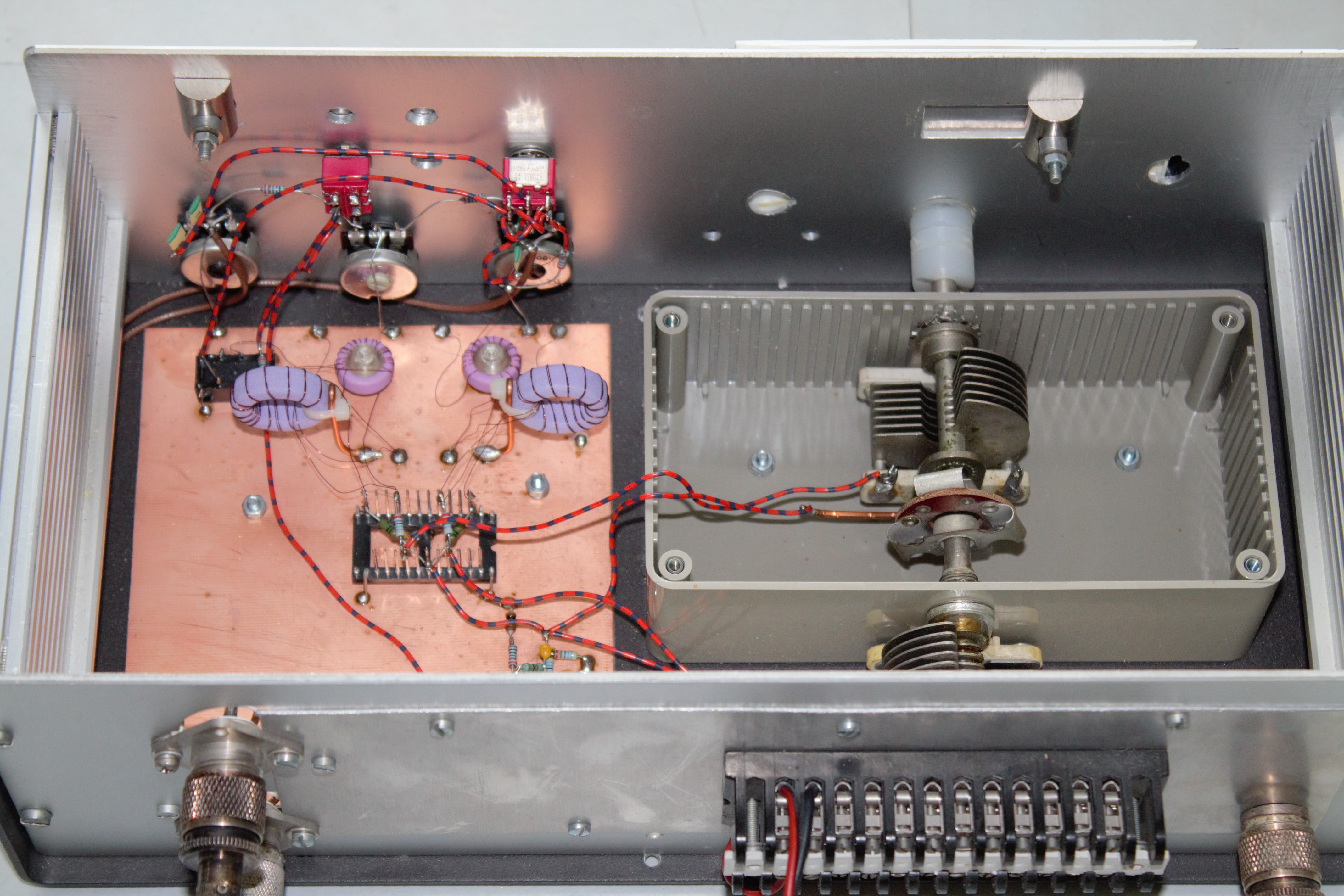
Because of the much better control of the phase difference and the gain ratio, it is much easier to get deep nulls. Knowledge of the actual phase setting, linear phase control and phase/gain spreading are a must.
Noise contribution is about the same as the MFJ-1025, because the phasing networks are essentially the same. But large signal behavior is much better.
Last updated: May 12, 2019
© PA0SIM