[Home] [Digital Signal Processing route] [Published Articles]
[Local QRM/noise reduction] [Very small vertical magnetic loop]
[Medium size vertical magnetic loop] [Vertical magnetic Alford loop]
[Vertical magnetic loops in real life] [Circular polarization]
[Broadband amplification] [Broadband amplifier] [Single chip amplifier]
[Dual loop antenna system] [Hints]
[Phaser 80 – 10 meters] [Balancing and closed loop antennas]
Broadband loop amplification (update May 2018)
Small magnetic loop circuit model
Broadband amplification for a short (capacitive) vertical or whip antenna is well known.
The same broadband amplification is possible for a magnetic loop, however with a different amplifier.
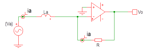
Basically a very small loop can be modelled as an inductor La and the induced signal voltage as a source Va. The loop is shorted by the virtual ground of the amplifier.
The output voltage:
![]()
And the induced voltage Va:
![]()
E [V/m] is the electric field, A [m2] the surface of the loop, c the speed of light and ω the frequency times 2π.
The output voltage Vo of the amplifier is:
![]()
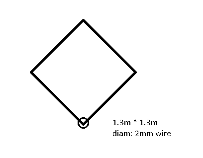
The loop dimensions
A loop however behaves only like an inductor as long as it is small compared to the wavelength.
Assuming a 1.3m×1.3m square loop with 2mm wire diameter with the feed point at the bottom, as used in combination with the broadband amplifier:
At frequencies higher than 15MHz it cannot be regarded as a small loop and as a single constant inductor.
Second best circuit model of the loop
A second best model uses besides the Va and the inductance La, also a capacitor and a resistance Ra:

The resistance Ra is frequency dependent. For small loops the free space radiation resistance:
![]()
The capacitor models the first parallel resonance 28MHz frequency. This frequency is mainly set by the size of the loop and less by the diameter of the wire. Parasitic inductances or capacitances also shift this frequency.
This model however does not show the second series resonance at 60MHz. At 60MHz the loop is a full wave quad and behaves like a full wave quad antenna. The feed point impedance is low (117Ohm).
There are two things to consider:
· The loop antenna current ia as a function of the electrical field E: for the induced antenna current the loop is shorted by the virtual ground of the amplifier.
· The loop gain of the amplifier: the loop gain of the amplifier sees the impedance of the loop and so the very high impedance at 28MHz and the low impedance at 60MHz.
Note: of course the impedance of the loop is also relevant for noise impedance matching.
Third improved circuit model of the loop using a transmission line
EZNEC is used to analyze the induced current and impedance behavior of the loop (4NEC2 can be used instead of EZNEC also).
This enables to compare the circuit models with the EZNEC results and see how well they match.
A model much better reflecting the loop impedance as seen by the amplifier and the current behavior for frequencies >15MHz, uses a transmission line instead of an inductor. Also in the actual loop antenna the current shows propagation delays just like in a transmission line.
At about 60MHz the loop is a full wave quad antenna.
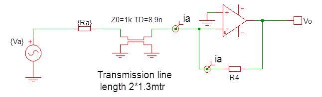
For frequencies <15MHz the model still behaves like an inductor.
At 56MHz transmission line is a ½ wavelength long and the input impedance for Va (left) is very low because it is shorted by the virtual ground of the amplifier. The current ia at the virtual ground equals the current through Ra.
At 28MHz the length is a ¼ wavelength. It is a bit counter intuitive that this resonance is not visible in the current ia at the amplifier. At 28MHz the transmission line is terminated with the low impedance virtual ground. The transmission line transforms this into a very high impedance at the input of Va on the left side. Because the input and output power of the transmission line has to be equal (no losses in the transmission line), the low input current is transformed into a high current ia at the virtual ground. If you do the math, you will see that the current ia is mainly set by the high characteristic impedance Z0 of the transmission line.
In the next figure the (for E normalized) current in the EZNEC model (blue) and the current in the circuit model (red) are compared:
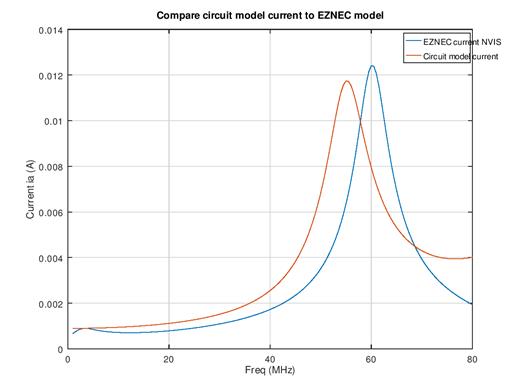
Note: In the EZNEC model a signal is selected with polarization and direction of arrival to fit the circuit response. Other polarizations and direction of arrivals show different plots!
Comparing the circuit model current to the actual current in the loop is very limited. On frequencies >15MHz the radiation pattern changes with frequency and the measured current in the loop is affected by:
· the not constant current distribution over the loop
· polarization of the signal
· direction of arrival of the signal
· the height of the loop above ground
· ground characteristics
Any circuit model can only be a rough average approximation for frequencies >15MHz.
For the design of the amplifier it is not necessary to improve the circuit model further.
Practical ambient noise measurement with the amplifier are used to verify the average behavior of the loop on broadband amplifier.
The resistance Ra is scaled with a factor 2 to better match the EZNEC results at frequencies >15MHz. That is acceptable, because at lower frequencies the resistance becomes increasingly less relevant for the application. However the used equation is only valid for very small loops. Mainly because the Ra is not correctly modeled, the loop impedance curves will not fit exactly.
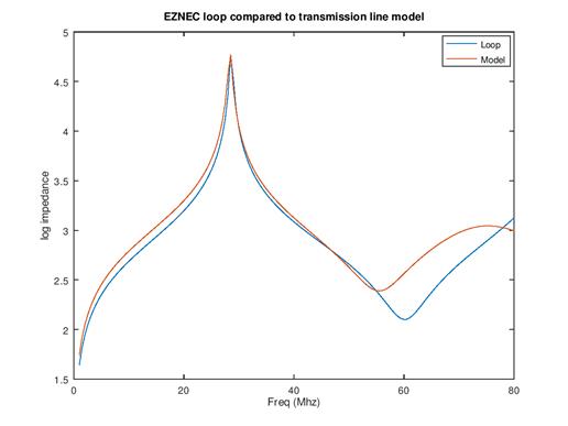
The impedance of the EZNEC loop (blue) and of the circuit model (red) are compared in the next plot:
Practical implementation of the loop (<30MHz)
The loop can be a circle or a square, it can be made with tubing or with a thin wire.
What counts is:
![]()
For example: a circular 1.35m diameter loop with a 10mm diameter tube is equal to a 1.35´1.35m square loop with a 2mm diameter wire.
Remark added May 2019:
What counts is the energy in the inductance of the loop: ia2 × La.
The amplifier not only needs noise impedance matching. The loop impedance is also relevant for large signal behavior via the loop gain in the amplifier. This applies to any amplifier.
In the broadband amplifier a transformer is used at the input of the amplifier. The primary inductance has to be scaled to the loop inductance (and so the number of turns to the square root).
Example: if you reduce the inductance La by a factor of 2, the number of turns on the primary side has to be reduced with a factor of 0.7. The current in the loop is 2 times higher, but because of the impedance matching the current into the amplifier is increased with a factor of 1.4. The result is that the signals are 1.4 time stronger (+3dB) with the same amplifier noise level and large signal behavior. In effect the input noise is decreased with 3dB.
Note:
Observe that the resistance of the wire is not in the equations. Normally the resistance is very much smaller than the ωLa and can be neglected.
When loops are tuned by a capacitor in a small band application, then the loss resistance is relevant for bandwidth and efficiency.
Last update: May 23, 2019
© PA0SIM