[Home]
[XOpropagation] [Circular Polarized TX Antenna Challenge]
Circular Polarized Transmit Antenna Challenge
Receiving
For receive only, e.g. 2 orthogonal small loops and an analog Phaser can do the job.
A phaser in DSP is of course preferred.
The phaser is used for summing both antenna signals with equal gains and a +/- 90 degree phase difference.
Switching between Left and Right hand is done by the invert/norm switch,
When the O wave is dominant (e.g. during day-time), the phaser is trimmed for maximum difference in signal level between invert and norm.
Transmitting
For transmitting (with larger antennas) it is not self-evident at all to have controlled circularity.
Circularity can be reduced by e.g.:
- incorrect tuning of elements (e.g. turnstile elements)
- coupling with nearby objects or antennas
- unbalancing
- antenna height
- sloping elements
- etc.
EZNEC+ or 4NEC2 is needed to evaluate designs and to learn about sensitivity.
And equally important the other way around, unbalancing can cause elliptical/circular polarization when using a linear polarized antenna!
One thing to remember is that only for short distance NVIS (<100km) circular polarization is needed straight up.
A solid measurement is reported in QST, January 2006, “Elevation Measurements During a Local Contest”, pg 28-30, by PA3DES, PA5BW, PA0SIR, PA0A.
However a lot of 80 meter communications is between 30 and 75 degrees elevation angle.
Besides turnstiles, loops, etc., more antennas then become suitable.
The next antenna is an example how easy it can be to build a circular polarized antenna for these elevation angles.
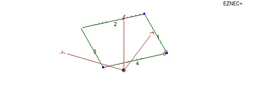
It is a 14 by 14 meters square loop, 20m diagonally (1/4 wavelength), height 8 meters.
EZNEC results at the best azimuth angle are:
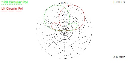
And at 65 degrees elevation:

At the elevation angles of interest good circularity is available but only in two directions.
Therefore it is necessary to select the correct corner for the feeding point.
The advantage of this directivity is directivity.
When only the O wave is present, the red plot (left hand polarization) is highly attenuated.
The green plot is the effective radiation pattern.
In this way circular polarization can be exploited!
BUT: 3dB (half of the power) is lost in the wrong direction.
By the way this antenna shows also how easy it is to have unintended circularity.
But for short distance NVIS you still need circular polarization straight up.
So if you need a new challenge …..
Last update: November 29, 2015
© PA0SIM