[Home] [Digital Signal Processing route] [Published Articles]
[Balancing and closed loop antennas]
[Balancing antennas] [Self balancing examples] [Antenna common mode impedance]
Self balancing examples
To show the self-balancing property of closed loop antennas I have modelled six representative and striking examples in EZNEC.
All examples are made worst case unbalanced by using a coaxial feeder, by not using a balun and by selecting the worst case feeder length and termination.
1. Half wave open dipole, transmitting, source on the dipole, coaxial feeder
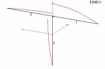
The coaxial feeder (wire 3) length is worst case 1/4 λ. The source is placed on wire 1 (small red dot). The wires 2 and 3 are connected at the feed point. The source is a 1A current source. At the feed point the currents on the wires 2 and 3 are 0.21A and 0.79A.
The current distribution can easily be understood when imagining the wires 2 and 3 as being radials. Then the antenna system looks like a 90° rotated ground-plane.
The coupling between dipole and coax is 20×log(0.79A/1A)= -2dB.
2. Quad, transmitting, source on the quad, coaxial feeder
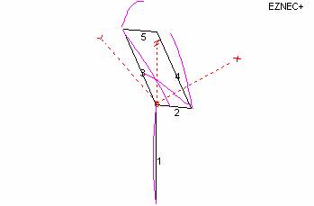
The coaxial feeder (wire 1) length is worst case 1/2 λ. The source is placed on wire 2 (small red dot) close to the feed point. The source is a 1A current source. The feed point impedance of the quad is 135 Ohm. So the total radiated power is 1×1×135=135Watt.
The maximum current on wire 1 is 0.1A. At that point the impedance is 145 Ohm. That makes 0.1×0.1×145=1.45Watt on the coax shield.
The coupling between quad and coax is 10×log(1,45/135)= -19.7dB.
3. Folded dipole, transmitting, source on the folded dipole, coaxial feeder
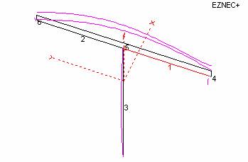
The coaxial feeder (wire 3) length is worst case 1/2 λ. The source is placed on wire 1 (small red dot) close to the feed point. The source is a 1A current source. The feed point impedance of the folded dipole is 265 Ohm. So the total radiated power is 1×1×265=265Watt.
The maximum current on wire 3 is 0.173A. At that point the impedance is about 75 Ohm. That makes 0.173×0.173×75=2.25Watt on the coax shield.
The coupling between folded dipole and coax is 10×log(2.25/265)= -20.7dB.
4. Half wave open dipole, receiving, noise source on coaxial feeder

The coaxial feeder (wire 3) length is worst case 1/4 λ. The noise source is placed on wire 3 (small red dot). The noise source is a 1A current source. The impedance of the receiver is placed at wire 1 close to the feed point. Just for this calculation 75 Ohm is used.
At the feed point the currents on the wires 1 and 2 are 0.3A and 0.7A.
The current distribution can easily be understood when imagining the wires 1 and 2 as being radials. Then the antenna system looks like a 180° rotated ground-plane (up side down). The current on wire 1 is reduced by the extra 75 Ohm impedance of the receiver.
According to EZNEC total radiated power is 48 Watt and 7 Watt shows up at the receiver impedance.
The coupling between coax and receiver is 10×log(7/48)= -8.4dB.
5. Quad, receiving, noise source on coaxial feeder
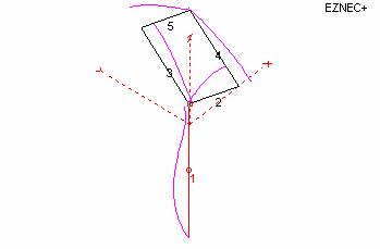
The coaxial feeder (wire 1) length is worst case 1/2 λ. The noise source is placed half-way on wire 1 (small red dot). The noise source is a 1A current source. The impedance of the receiver is placed at wire 2 close to the feed point. Just for this calculation 135 Ohm is used.
At the source the impedance is 145 Ohm, so the total radiated power is 1×1×145 = 145Watt.
The current at the feed point of the quad is 0.089A, so the received power is 0.089×0.089×135 = 1.06 Watt. The current distribution in the left side (wires 3 and 5) and in the right side (wires 2 and 4) of the quad is equal!
The coupling between coax and receiver is 10×log(1.06/145)= -21.4dB.
6. Folded dipole, receiving, noise source on coaxial feeder
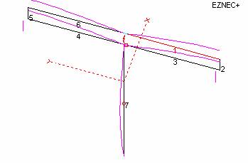
The coaxial feeder (wire 7) length is worst case 1/2 λ. The noise source is placed half-way on wire 7 (small red dot). The noise source is a 1A current source. The impedance of the receiver is placed at wire 3 close to the feed point. Just for this calculation 288 Ohm is used.
At the source the impedance is 75 Ohm, so the total radiated power is 1×1×75 = 75Watt.
The current at the feed point of the quad is 0.026A, so the received power is 0.026×0.026×288 = 0.192 Watt.
The coupling between coax and receiver is 10×log(0.192/75)= -25.9dB.
Summary
In a worst case unbalanced situation (no balun, coaxial feeder with worst case length and termination):
1. Half wave open dipole, transmitting, source on the dipole, coaxial feeder
The coupling between dipole and coax is -2dB.
2. Quad, transmitting, source on the quad, coaxial feeder
The coupling between quad and coax is -19.7dB.
3. Folded dipole, transmitting, source on the folded dipole, coaxial feeder
The coupling between folded dipole and coax is -20.7dB.
4. Half wave open dipole, receiving, noise source on coaxial feeder
The coupling between coax and receiver is -8.4dB.
5. Quad, receiving, noise source on coaxial feeder
The coupling between coax and receiver is -21.4dB.
6. Folded dipole, receiving, noise source on coaxial feeder
The coupling between coax and receiver is -25.9dB.
Last update: March 3, 2007
© PA0SIM