[Home]
[QEX] [GNU radio NC]
Stereo Diversity and Noise Cancelling using GNU Radio Companion (update Dec. 2022)
Functionality is extended to:
- Stereo diversity with two orthogonal antennas, like a turnstile antenna, using the linear polarized A/B signals of both antennas or the derived X/O circular polarized signals
- The amplitude ratio and phase difference of the A/B or X/O signals is plotted
- Noise cancelling is possible on the A/B or the X/O signals
- S-meters added for both A/B or X/O signals.
Noise cancelling is implemented in a “one mouse click” like way as described in the March/April 2019 issue of QEX. However because the mouse cursor location is not available in GNU radio companion blocks the “one mouse click noise canceller” is implemented by using two sliders for setting the Phase difference and amplitude Ratio.
=> The GNURadio 3.8 model is in SD_NC_ABX)_zip (including demo audio files).
What is needed:
- Two identical phase coherent receivers like the ANAN200D, SDRplay RSPduo, Flexradio 6600/6700 or Elecraft K3/K4 * See Note 1 at the end of the page
- The stereo output audio signal of both receivers with the AGC switched off
- The stereo audio PC/laptop input via e.g. an external soundcard (fs=48kHz)
- GNU Radio Companion 3.8
- Two receiving antennas or two identical orthogonal antennas like a turnstile
The implementation also supports the use of an audio file as input source. Some demo files are included in de zip file.
Note: The model will run without receivers using these demo files.
For effective noise cancelling both antennas have to receive the man-made noise source (QRM).
In the QEX article two orthogonal identical active small receiving loops are used.
However the main transmit antenna can also be used in combination with e.g. an active whip antenna. The antenna with the strongest man-made noise is assumed to be the noise pickup antenna. For best performance the amplitude level of the noise source on the whip antenna should be strongest.
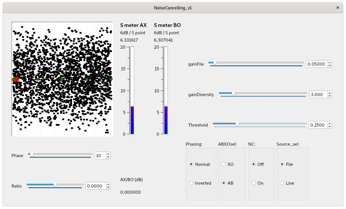
The plot displays for the strongest frequency components (FFT bins) in the audio band the amplitude ratio R (Y axes) and the phase difference P (X axes) between the two A/B or X/O signals. Each dot represents a measurement of one frequency component. P and R are the coordinates in the plot.
![]()
It is not practical to use the amplitude ratio directly. If the amplitude of antenna A is |A| and of antenna B is |B| the ratio is set by:
![]()
This allows one of the signals to be zero.
When only noise is present all dots in the plot are randomly spread over the plot (assuming both antennas have different polarization and the same noise floor level as with the two orthogonal loops!):
When a single man-made noise source is present the dots will be concentrated around the corresponding phase difference P and amplitude ratio R. See next plot.
With increasing amplitude of the man-made noise source the dots will be increasingly concentrated. This also applies to signals, because a man-made noise source in fact is also a signal.
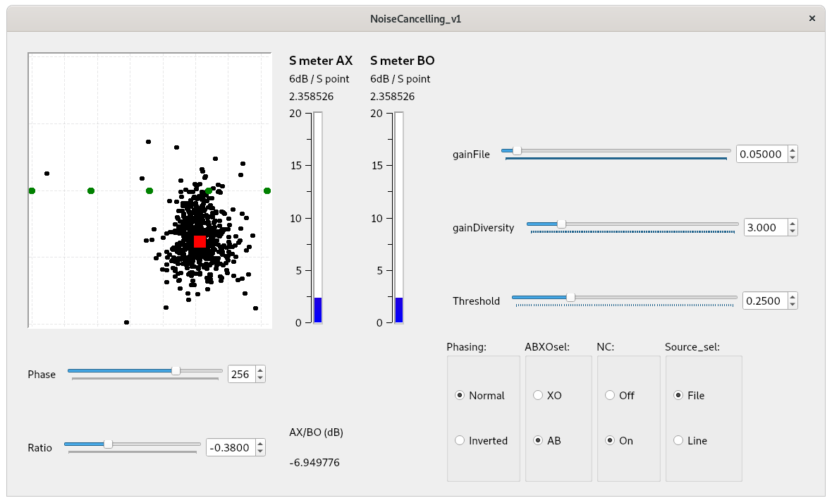
The red dot represents the phase P and ratio R setting for noise cancelling.
When hovering the mouse cursor over the plot the amplitude ratio R and phase difference P values are shown. This helps setting the sliders for the phase difference and amplitude ratio.
The green dots are markers for 0°, 90°, 180°, 270° and 360° phase difference.
The gainDiversity and gainFile set the gain for the input of the receivers and for the input of the audio file.
The Phasing selection allows for inverting the noise cancelling and so enhancing the noise source (or a signal).
The AB/XO indicator shows the ratio setting as the ratio in dB’s between the A/B signal or the X/O signal amplitudes.
The plotting for the noise cancelling setting and polarization information is done in the frequency domain. The noise cancelling function itself is done in the time domain to minimize latency.
A screen recording of received O wave signals is in screenrecording_Owave.mp4
It shows how the practically circular polarized O wave signal is plotted and how it can be “noise cancelled” or “enhanced”. Stereo diversity of the A/B signals or the X/O signals can be selected. A simple AGC is used to have equal gain for both stereo channels.
Note 1
No equalizing function is implemented to correct for differences between the two receivers of the SDR radio. Assumed is that both receivers are identical and settings are equal. E.g. in PowerSDR bandpass filtering can be set different for both receivers. Also soundcard channels will not be exactly equal. Any difference reduces the achievable depth of the noise cancelling!
Equalizing can be done by e.g. adaptive filters and applying a single noise source to the inputs of both receivers to equalize.
Note 2
Normally much different antennas are used for noise cancelling with different signal levels.
A gain balancing setting will be needed to equal the signal levels. This is not implemented in the model.
Note 3
The plot is also a measurement tool, because signals and identifiable noise sources reveal itself as a cloud of dots. The plot shows:
- if it is a suitable combination of antennas for noise cancelling
- if the antenna combination is behaving as intended
- if signals overlap with the noise source and both will be cancelled
- polarization behavior of received signals
Installing GNURadio 3.8:
Installing GNUradio 3.8 on Linux Debian 11 is straight forward:
$ sudo apt-get install gnuradio
Installing GNURadio 3.8 on Windows 10:
http://www.gcndevelopment.com/gnuradio/index.htm
Note: may be the audio source block is not working correctly.
In the next directory a file "gr-audio.conf" has to be present:
C:\Program Files\GNURadio-3.8\etc\gnuradio\conf.d
Edit in this file:
[audio]
audio_module = portaudio
[up]
Last update: December 23, 2022
© PA0SIM